Verilog defines four logic value sets: logic zero (0), logic one (1), logic don't care (X), and logic high impedance (Z). The simulator analyzes these values as follows: logic zero and logic one represent clear binary states (false and true respectively), while logic don't care (X) represents an unknown state that can be either 0 or 1, and logic high impedance (Z) represents neither 0 nor 1, typically occurring when a tri-state buffer is disabled. When simulating, the simulator cannot resolve conflicts between competing signals (like 1 and 0 fighting), resulting in an unknown (X) value, and when a tri-state buffer's enable is inactive, the output becomes high impedance (Z) because the simulator cannot determine whether the output is 0 or 1.
1_How Simulators analyze Logic Sets in VerilogAdded:
Hi everyone. Welcome to my first video in this Verilog series. So today I will be discussing something about the different value sets in Verilog.
As we are already aware, there are four different value sets defined in Verilog.
Zero, logic zero, logic one, logic don't care, logic high impedance, Z Z.
So logic zero is nothing but we are going to assume it as logic low or false condition.
Logic one is nothing but it's logic high or true condition.
Logic don't care is nothing but it's an unknown.
And logic Z is nothing but it's an high impedance.
High impedance, okay?
So generally, whenever we assume logic zero and logic one, everyone will be having that enough clarity.
But now in this video, let us try to analyze how the simulator will analyze this different logic sets inside any Verilog compiler or anything.
So in the simple terms, if we want to discuss what is a don't care, it is nothing but either one or zero.
And in the simple terms, if you want me to explain what is an high impedance, it is nothing but it's neither one nor zero.
So, this will be the conditions.
Okay?
Now, let us try to assume how the simulator will analyze.
Analysis of logic sets in Verilog.
Okay?
So, generally, the first one, let us start with a basic one, the logic zero.
So, >> [snorts] >> so whatever the analysis which I'm going to start here will be nothing but we are going to as it is a simulation, we will be considering the ideal analysis.
We will be considering the ideal cases.
So, what does it mean by the ideal cases?
First one, no delay for the buffer.
No noise margin into consideration.
Okay?
So, now, let us come back to a scenario where how the logic zero is being analyzed by the simulator Verilog in Verilog.
So, whenever we are considering anything, let me just assume a buffer.
So, so what is the functionality of a buffer? Whatever the input we are giving, we are going to get the same output. Okay? So, as we have discussed earlier, by the till the end of this video, whatever the buffer we are going to discuss will be nothing but the ideal buffer.
So, so now, if at all, I'm giving an ground here, the output will be zero, which is equals to logic zero.
Now, let us analyze how the logic one works.
How the logic one works.
Let me as again assume a buffer.
Let me again assume a buffer.
So, let me give the VDD as the input.
So, just to analyze it's a VDD.
So, whenever I'm giving the input of VDD to a buffer, obviously whatever the output which I will be receiving will be nothing but one. Nothing but the logic one or logic high, anything.
Now, the next one comes, the most interesting one is the logic don't care.
The value set don't care.
Value set.
Okay?
So, what does it mean by a don't care?
Already in the above discussion, we made a statement like logic don't care is nothing but either one or zero.
So, in order to analyze this, let us go with an idea like how the simulator will work.
So, let me assume a buffer over here.
Let me assume an another buffer over here.
So, here let us consider whatever the input which we are giving is nothing but VDD.
So, obviously as per our above analysis, the output will be one.
So, here let us assume whatever the input which we are giving is nothing but ground.
So, the output with this one will be the zero.
Now, when both of them are connected, there is a fight between one and zero.
As the we have considered everything to be ideal, the simulator and everything to be the ideal thing, there is a fight between one and zero. So, the simulator cannot decide which one comes first and which one comes later. So, obviously initially, whenever the simulator is unable to decide between one and zero, so obviously it will give an unknown because it doesn't know who will win the race.
So, that's how we will get something called as unknown or don't care logic value set don't care.
So, now if we can go for the logic high impedance value set.
Logic high impedance value set.
So, generally for this, already we made a discussion like it is nothing but neither one nor zero.
Okay? So, whenever we call this one as neither one nor zero, automatically it is nothing but So, let me take the help of an tri-state buffer.
So, what does it mean by the tri-state buffer? So, let us assume there is a buffer.
Let us assume there is a Sorry. Let us assume there is a buffer.
So, this will be the input. This will be the output.
So, this will be the enable.
So, generally how the tri-state buffer works?
Whatever the output will be assigned with the value of the input only under the condition when enable equals to one.
But, what if enable equals to zero?
The output, there will be no connection between the input and the output.
So, which leads to neither one nor zero because the simulator is not in a position to analyze whether that is one or zero. So, that's the reason we will get a value high impedance.
So, So is how the simulators will analyze all the different four logic sets. This analysis has been very important or crucial in whatever my experience to debug so many things with respect to this.
So thank you. Thank you for your attention. If you are having any video ideas, please do comment below. I will be always ready to do something very new with respect to this. And this Verilog series will be continuing and I will try to make the as enough videos as possible. Please like, share, and subscribe to Beacon Preceptor.
And wait for more very good happy, knowledgeable content in Verilog and digital electronics.
Thank you. Thank you, everyone. Thanks once again. Have a great day.
Related Videos

Agentforce NOW AMA: Build with React and Salesforce Multi-Framework
SalesforceDevs
490 views•2026-05-28

How agent o11y differs from traditional o11y — Phil Hetzel, Braintrust
aiDotEngineer
450 views•2026-05-28

WEB TECHNOLOGIES UNIT-2 | Degree 4th sem BCOM Computers web technologies unit-2 full explanation💯✅
LearnwithSahera
1K views•2026-05-29

More tests are always better? How to use AI to identify tests that bring little value
Alliance4Qualification
335 views•2026-05-29

Search Algorithms Explained in 60 Seconds! 🤖💨
samarthtuliofficial
218 views•2026-06-01
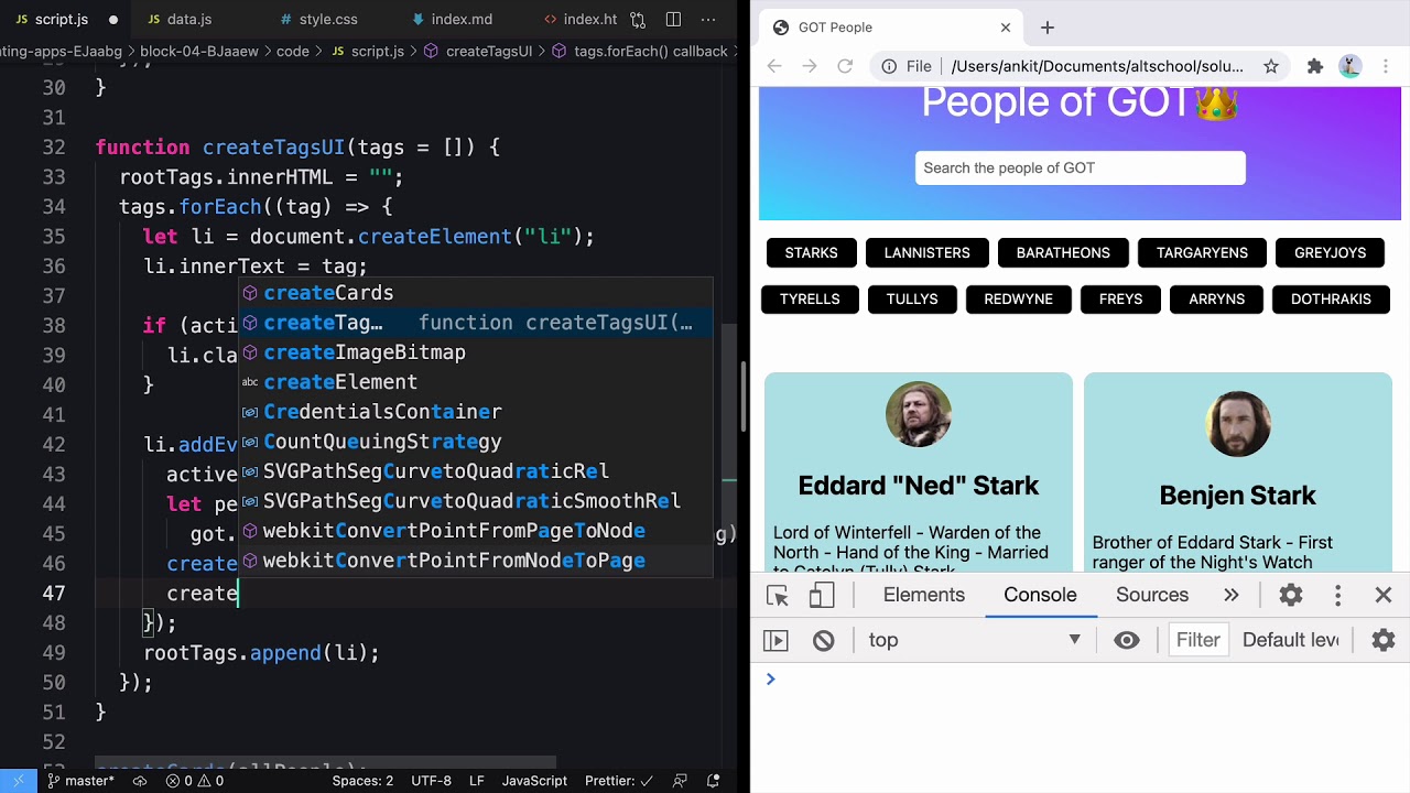
People of Game of Thrones using JavaScript DOM
AltCampus
296 views•2026-05-30

Introduction to Problem Solving Part - 1 | Lecture 1 | Intermediate DSA
ascensionix
107 views•2026-05-29

So What's Odin Lang Even Good For
TechOverTea
131 views•2026-06-01


