This lesson explains the different data types used in 3D scanning and CAD conversion: point clouds (raw scan data with or without normal vectors for shading), mesh files (triangular surfaces connecting points), auto surface bodies (direct scan-to-CAD conversion with high accuracy), and design intent solids (simplified CAD files with recognizable geometric features like cylinders and planes that can be dimensioned). The lesson emphasizes that proper import through the Geomagic for SolidWorks import dialogue is essential for full functionality, as standard SolidWorks open treats files as graphics files with limited editing capabilities.
Install our extension to search inside any video instantly.
Data TypesAdded:
[Music] This is lesson three. The data types begin. We're going to start this file by opening up an existing Solid Works document, which is 3A, the data type solid part. When I open this up, I can see that I've got several different objects already in my history tree. Some are point clouds, one's a mesh, and a couple are CAD bodies. It's going to ask me if I want to proceed with feature recognition. In this case, I'm going to select no.
The first body that we see on the screen is all black. This indicates that it is a point cloud that has been imported without normals. Now, normals are essentially a way to tell the user and the software what direction is out. So, every single point on a point cloud typically will have um besides its XYZ position, it will always also have an JK uh normal vector value that indicates, you know, if I'm scanning the part from the inside out or the outside in. In this case, we don't have those. So, the part cannot be shaded as is. I can of course change the object colors around, but I still don't get any real shading here. All of the points are the same color regardless of whether or not the the light's shining on them.
We can still work with this. We can wrap it and turn it into a mesh body. Um, but usually when we're scanning, we actually scan a point cloud with normals. So, I'm going to rightclick the point cloud with normals option in my history tree and use the show command to show that. So, this is still a point cloud. It's actually the same point cloud. It just had normal values in it. And you can see that it's shaded a lot more realistically. It looks more like a real object. If I zoom in close enough, I can see that I've got individual points. And I can also see through the object. So, I can actually see the backside of the points behind. And that's going to be shaded in that yellow color.
Now, like I said, both of these point cloud formats can and often should be converted either using the wrap command or the merge tool, which we'll talk about later, into a mesh file. This mesh file here, which I'll show next, is indicated by a different icon in the history tree with this little blue pyramid.
This mesh I uh or the mesh body is a series of the same points but they're wrapped uh with triangular edges that kind of connect the dots from all the point cloud uh and they are converted into triangular surfaces. If I go to my show tool here and show my edges, I can see the collection of triangles that make up that mesh. When we're doing reverse engineering inside of the geometric for Solid Works plugin, we always use a mesh file.
The next type of file that we'll deal with is going to be a CAD file. This is something that we generally create. This is kind of the point of the plugin is to convert this mesh object into a CAD file. If I rightclick my next object here, which is my scanned mesh autosurface, I can show that. And what I see is a collection of ners surfaces that have been wrapped around the mesh to the right. This net looks kind of like a spiderweb and it's a direct conversion from the mesh here to CAD body. Now the advantages of a auto surface body is that it's generally very quick to accomplish this. Um and it's also very accurate to the scan data. The deviation here is is very low because it is a direct scan to CAD conversion.
The next type of file that I have is the design intent solid. If I show that, you can see the difference between the design intent body and the body to the right. I have fewer surfaces and I also have surfaces that can be recognized as planer, cylindrical, that type of thing.
These planer and c cylindrical features can be dimensioned. And this is great a little bit more for mechanical objects, things that are going to go into maybe a CNC machine and be cut uh and things that need mechanical features like cylinders.
Now, there's a type of file that I don't have in here right now that I'm going to bring in next. I'm going to bring this in using the import dialogue inside of the Geomagic for Solid Works tab. Now, it's very important that we use this import dialogue inside of the tab rather than using the Solid Works open. If I use file open, most of our customers are going to be aware that we do have the ability to bring in point clouds and meshes into Solid Works already. If I use the Solid Works tool and I select this 3B CAD converted mesh and hit open, I can see that I do have my mesh inside of Solid Works. The problem is is that this is considered a graphics file inside of Solid Works and there's not much that I can do with it.
I can't edit the feature. I don't have that option. And you can see that none of the geometric for Solid Works mesh processing tools are enabled. That's because we need to use the Geomagic for Solid Works import tool to be able to interact with this data. The other problem is it comes in in its own separate window. So we can't work on multiple files at the same time. So, what I'm going to do is I'm going to close this window and I'm going to use the geometric for Solid Works import command to import the same file. And we'll see what the difference is here.
When I do that, I'm going to hide my design intent solid because they're overlaid.
And I can see the difference between, see, hide all of my solids here. I can see the difference between this file which is converted from a CAD body and this file which comes from a scanner. I have a lot fewer triangles, a lot sharper triangles on my CAD converted solid. And if I hide my edges here, I can actually see I do have sharp edges, which is not something that I see on the scan file.
One of the other things that we'll notice if I go back to hiding all of my meshes all and showing my solid and uh solid bodies here is that the two objects are a little bit different.
What I have on the left is a design modification. I can't do design modifications to much degree when I'm using the autosurface command because it's a direct uh conversion from the scan data to the CAD. I don't really have any flexibility in adding or changing any of the features. So in this case, we've actually modified the design, changed the base around a little bit, and we're able to do that because we're not limited to the quality or just the general nicities of the scan data. So that's one of the benefits for working with the CAD design intent file.
[Music]
Related Videos

Agentforce NOW AMA: Build with React and Salesforce Multi-Framework
SalesforceDevs
490 views•2026-05-28

How agent o11y differs from traditional o11y — Phil Hetzel, Braintrust
aiDotEngineer
450 views•2026-05-28

WEB TECHNOLOGIES UNIT-2 | Degree 4th sem BCOM Computers web technologies unit-2 full explanation💯✅
LearnwithSahera
1K views•2026-05-29

More tests are always better? How to use AI to identify tests that bring little value
Alliance4Qualification
335 views•2026-05-29

Search Algorithms Explained in 60 Seconds! 🤖💨
samarthtuliofficial
218 views•2026-06-01
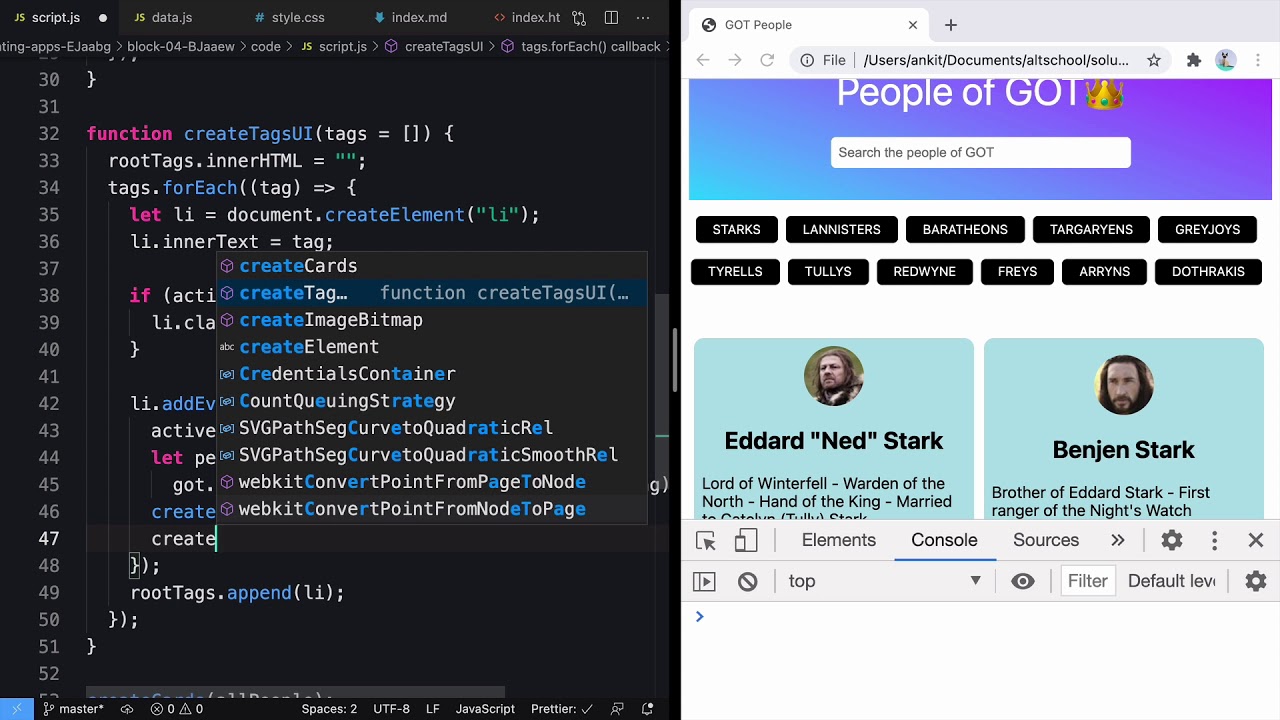
People of Game of Thrones using JavaScript DOM
AltCampus
296 views•2026-05-30

Introduction to Problem Solving Part - 1 | Lecture 1 | Intermediate DSA
ascensionix
107 views•2026-05-29

So What's Odin Lang Even Good For
TechOverTea
131 views•2026-06-01


